




 74 / 221

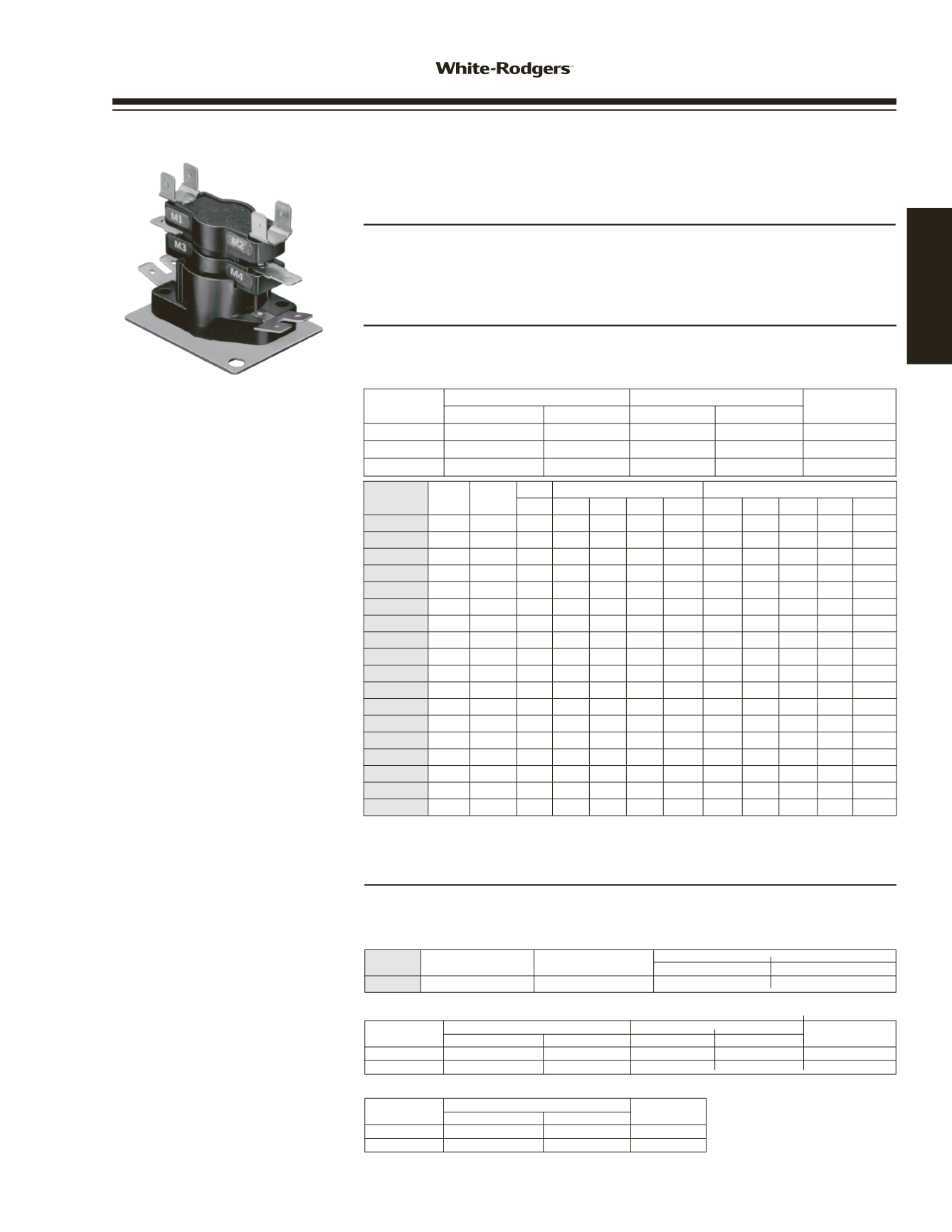
TABLE NOTES
:
➀
M1-M2 and M3-M4 are always first switches
to turn ON and last to turn OFF. All other
switches are random ON and random OFF
➁
24A34-14 Switch contacts designated
F
1
- F
2
instead of M
1
- M
2
➂
24A34-28 is 2 pole double throw
♦
These contacts switch simultaneously
NOTE
: Underwriters Laboratories requires a
fan interlock circuit to insure the blower
remains operating whenever more than one
sequencer is used. The fan interlock should
be the M
1
/ M
2
contacts of the second or third
sequencer.
All M
1
/ M
2
contacts are wired to the blower
motor so that any sequencer that is energized
will keep the blower ON.
COMBINED LOAD RATING TABLE
(ALL MODELS)
30A @ 240 VAC – TOTAL,
23A Non-Inductive + 7 FLA / 42 LRA Inductive,
ON Time: Elapsed time to make contacts after
heater is energized (min. to max.)
OFF Time: Elapsed time to break contacts after
heater is de-energized (min. to max.)
24A34-3
Model
Timings
Number
Timings
Switches
ON 1-3
OFF 1-3
24A34-15
1
1
1-60
75-95
24A34-15 HEAT PUMP CONTROL
FEATURES
• Used in heat pump air handler applications.
• Provides a delay off to the blower motor in cooling mode.
• Single pole double throw.
Resistive (Non-Inductive)
Motor Ratings (Inductive)
VAC
Watts
Amps
Full Load Locked Rotor
Pilot Duty
120
3000
25.0
14.0A
72.0A
125 VA
240
6000
25.0
7.0A
42.0A
125 VA
ELECTRICAL RATINGS – NORMALLY OPEN CONTACTS 1-3
Resistive (Non-Inductive)
VAC
Watts
Amps
Pilot Duty
120
1200
10.0
125 VA
240
1200
5.0
125 VA
ELECTRICAL RATINGS – NORMALLY CLOSED CONTACTS 1-2
ELECTRIC HEAT
PRODUCTS
HEAT
SEQUENCERS
Indicates Canadian Model Number: call 1-800-305-6953 to order
24A34 SERIES ELECTRIC HEAT SEQUENCERS
Direct Replacement for Most Fan / Heat Sequencing Functions.
Terminal Markings are Equivalent to Competitive Types
FEATURES
• Replaces Honeywell, MARS, TOD,
• Any contacts (except M1 & M2) can be
GEMLINE, Klixon (Texas Instruments).
used as auxiliary contacts.
• 24V input control.
• Double quick-connect terminals for
• Multi-poise mounting.
combination loads.
SPECIFICATIONS
Ambient Temperature Rating . . . . . -50 to +165°F
Agency . . . . . . . . . . . . . . . . . . . . . . . . . . . U.L. component recognized
ELECTRICAL RATINGS – SINGLE LOAD CONTACT RATINGS (ALL MODELS)
VAC
Resistive (Non-Inductive)
Motor Ratings (Inductive)
Pilot Duty
Watts
Amps
Full Load Locked Rotor
120
3000
25.0
14.0A
72.0A
125 VA
240
6000
25.0
7.0A
42.0A
125 VA
480
6000
12.5
–
–
480 VA
Model
Number Timings Switches
Timings – ON
Timings – OFF
M1-M2 M3-M4 M5-M6 M7-M8 M9-M10 M1-M2 M3-M4 M5-M6 M7-M8 M9-M10
24A34-1
1
1 1-20 –
–
–
– 40-110 –
–
–
–
24A34-2
1
1
–
– 30-90 –
–
–
– 1-30 –
–
24A34-3
➀
1
2 1-20 1-20 –
–
–
40-110 40-110
–
–
–
24A34-4
1
2
–
– 30-90 30-90 –
–
– 1-30 1-30 –
24A34-5
➀
2
3 1-110 1-110 1-110 –
– 1-110 1-110 1-110 –
–
24A34-6
➀
2
4 1-110 1-110 1-110 1-110 – 1-110 1-110 1-110 1-110 –
24A34-14
➀➁
4
5 1-160 1-160 1-160 1-160 1-160 1-160 1-160 1-160 1-160 1-160
24A34-21
1
1 1-20 –
–
–
– 1-50 –
–
–
–
24A34-22
1
1 15-45 –
–
–
– 1-30 –
–
–
–
24A34-23
1
1 25-55 –
–
–
– 15-45 –
–
–
–
24A34-24
1
1 30-75 –
–
–
– 1-40 –
–
–
–
24A34-25
1
1 40-90 –
–
–
– 1-30 –
–
–
–
24A34-26
2
2 1-20 30-90 –
–
– 40-90 1-30 –
–
–
24A34-27
2
2 1-160 1-160 –
–
– 1-160 1-160 –
–
–
24A34-28
➂
2
2 1-160 1-160 –
–
– 1-160 1-160 –
–
–
24A34-29
1
1 15-35 –
–
–
– 25-55 –
–
–
–
24A34-36
2
2 1-20 30-45 –
–
– 45-110 1-30 –
–
–
24A34-37
1
1 1-110 –
–
–
– 1-110 –
–
–
–
♦
♦
♦
♦
♦
♦
♦
♦
♦
♦
♦
♦
www.white-rodgers.com75
HEATING