




 40 / 221

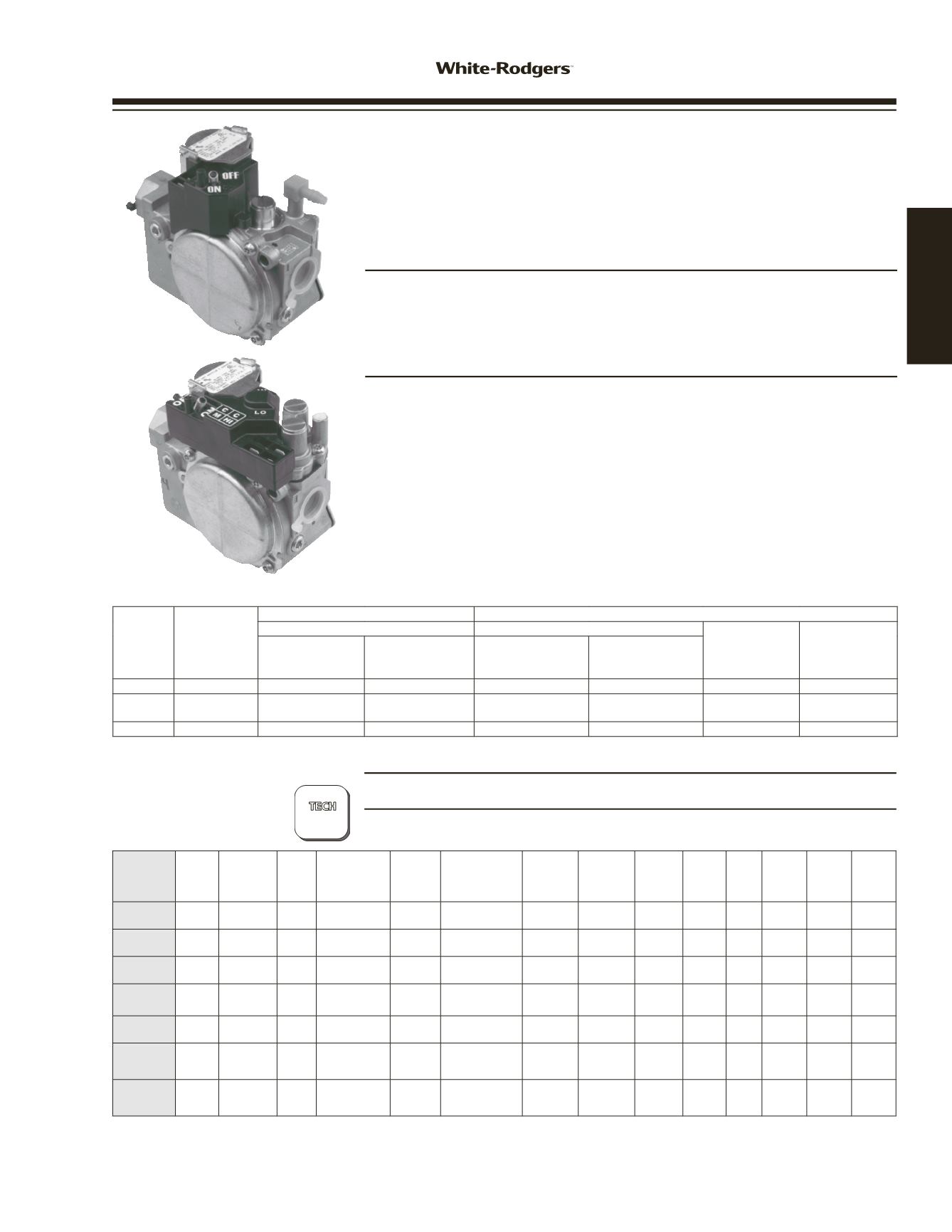
36G, 36J SERIES
GAS VALVES
GAS BURNER
CONTROLS
PARTS AND ACCESSORIES
See end of this section for parts and accessories
TECHNICAL HELP
Wiring Diagrams . . . . . . . . . . . See page 178
?
36J Series
page
178
36G, 36J SERIES GAS VALVES
The 36G, 36J is a Combination Gas Control Valve Designed for
Use with Non-Piloted Intermittent Ignition Systems. The Control
is Designed to Meet Today’s Maximum Capacity, Smaller Size
and High Efficiency Gas Systems
FEATURES
• Inlet and outlet screens.
• Quiet redundant.
• Built-in pressure tap.
• Quick-connect terminals (
1
/
4
”
).
SPECIFICATIONS
Ambient Temperature . . . . . . . . -40 to 175°F
Maximum Pressure Rating . . . . . .
1
/
2
”
PSI (14.0
”
W.C.)
Capacity (1
”
P.D.) . . . . . . . . . Natural 140,000 Btu/Hr.
L.P. 226,800 Btu/Hr.
Electrical Rating . . . . . . . . . . . . . . . . . . . . Single stage 24V, 50 / 60Hz at .3A
Two stage at .43A
Swing Radius . . . . . . . . . . . . . . . . . . . . . . 2.75
”
Mounting . . . . . . . . . . . . . Any position
Agency . . . . . . . . . . . . . . . . . . . . . . . . . . . C.S.A. approved
Valve
(Stages)
Pipe Size
1
”
Pressure Drop Capacity
Range of Regulation
BTU/HR
BTU/HR
Adjustment
Range
(Nat. IN. W.C.)
Adjustment
Range
(L.P. IN. W.C.)
Std. Gas
.64 Sp. Gr.
(1000 BTU/CU. FT.)
LP Gas
1.53 Sp. Gr.
(2500 BTU/FT.)
Std Gas
.64 Sp. Gr.
(1000 BTU/CU. FT.)
LP Gas
1.53 Sp. Gr.
(2500 BTU/FT.)
Single 1/2
”
x 1/2
”
NPT 140,000 BTU/HR 226,800 BTU/HR 40,000-210,000
60,000-340,000
2.5
”
-5.0
”
7.0
”
-12.0
”
Two 1/2
”
x 1/2
”
NPT 140,000 BTU/HR 226,800 BTU/HR
20,000 Low-
210,000 High
32,000 Low-
340,000 High
1.0
”
-4.0
”
Low
2.0
”
-5.0
”
High
4.0
”
-10.0
”
Low
6.0
”
-12.0
”
High
Modulating 1/2
”
x 1/2
”
NPT 140,000 BTU/HR 226,800 BTU/HR 20,000 - 210,000
32,600 - 340,000
0.40
”
-4.0
”
1.3
”
-11.5
”
Model
Number
Coil
Voltage Gas Type
Pipe
Size
Opening
Characteristic
Regulator
Setting
Regulator
Adjustment
Range
Convertible
Nat. / LP
LP
Conversion
Kit
Included
Flow
Direction
Reducer
Bushing
Kit
Filter
Screen
Inlet
Pressure
Tap
Outlet
Pressure
Tap
Internal
Wiring
See
Figure
➀
36G22-254
24 VAC Natural or
LP
1
/
2
x
1
/
2
Fast Opening
Single Stage
3.5
”
Nat. 2.5
”
- 5.0
”
L.P. 7.0
”
- 12.0
”
Yes
No** Str. Thru No Yes Yes Yes*
1
36J22-214
24 VAC Natural or
LP
1
/
2
x
1
/
2
Fast Opening
Single Stage
3.5
”
Nat. 2.5
”
- 5.0
”
L.P. 7.0
”
- 12.0
”
Yes
Yes Str. Thru Yes Yes Yes Yes
1
36J24-214
24 VAC Natural or
LP
1
/
2
x
1
/
2
Slow Opening
Single Stage
3.5
”
Nat. 2.5
”
- 5.0
”
L.P. 7.0
”
- 12.0
”
Yes
Yes Str. Thru Yes Yes Yes Yes
1
36J54-214
24 VAC Natural or
LP
1
/
2
x
1
/
2
Two-Stage
Fast Opening
LO 1.5
”
HI 3.5”
Nat. 2.5
”
- 5.0
”
L.P. 6.0
”
- 12.0
”
Yes
Yes Str. Thru Yes Yes Yes Yes*
2
36J55-214
24 VAC Natural or
LP
1
/
2
x
1
/
2
Two-Stage
Slow Opening
3.5
”
Nat. 2.5
”
- 5.0
”
L.P. 6.0
”
- 12.0
”
Yes
Yes Str. Thru Yes Yes Yes Yes*
2
36J24-614
24 VAC Natural or
LP
1
/
2
x
1
/
2
Single Stage
Slow Opening
3.5
”
Nat. 2.5
”
- 5.0
”
L.P. 7.0
”
- 12.0
”
Yes
Yes
90
o
Bottom
Outlet
No Yes Yes Yes*
2
36J55-614
24 VAC Natural or
LP
1
/
2
x
1
/
2
Two-Stage
Slow Opening
3.5
”
Nat. 2.5
”
- 5.0
”
L.P. 6.0
”
- 12.0
”
Yes
Yes
90
o
Bottom
Outlet
No Yes Yes Yes*
2
* To measure outlet pressure on valves, loosen outlet pressure tap screw one quarter turn and put manometer hose over the top of the outlet pressure tap.
** Use F92-0659 to convert to regulated L.P. gas
➀
Wiring diagrams – see page 178
www.white-rodgers.com41
HEATING